Launching into my wind tunnel adventures, the inaugural experiment demanded a meticulously crafted airfoil. For this, I utilized wing profiles I had previously 3D printed, destined for a model plane project. These profiles were joined using transparent tape, molding them into a cohesive airfoil shape. Hot glue has proven to be an indispensable ally; it came to the rescue once again, securing the profiles to a custom-designed wing spar with precision and durability.
To integrate a touch of functionality, I affixed a metallic attachment point, complete with a diminutive hole, ready to accommodate the servo control mechanism. This setup not only prepared my airfoil for the rigorous tests ahead but also embodied the blend of creativity and technical savvy that defines the spirit of experimental aerodynamics.

Once mounted to the test chamber, I got to run the first end-to-end tests, all controlled with my laptop running the Arduino IDE.

The initial foray into wind tunnel testing yielded promising results. Throughout this process, I encountered and resolved numerous software glitches, each resolution bringing a deeper understanding of the intricate dance between technology and aerodynamics. One of the most enlightening revelations was mastering the translation of servo angles—spanning from 0 to 180 degrees—into meaningful angles of attack, the crux of our aerodynamic investigations.
Calibrating the lift and drag load cells presented its own set of challenges, requiring a meticulous approach to ensure accuracy in our measurements. Additionally, learning to incrementally adjust the angle of attack with the servos, while simultaneously gathering and preparing data for export, proved to be an invaluable skill in our experimental arsenal.
A particularly vexing issue was the power supply to the Arduino. Initially, I had optimistically powered two load cells, the servo, and the Arduino itself solely from the Arduino’s 5V output. This optimistic configuration led to underwhelming servo performance, characterized by slow movements and, at times, complete unresponsiveness.

Image From Amazon
The breakthrough came with the introduction of a dedicated 9V power supply, sourced from Amazon. This not only revitalized the servo’s responsiveness but also enhanced the overall stability and reliability of our experimental setup. This series of adjustments and improvements underscored the iterative nature of experimental science, where each challenge surmounted brings us closer to the precision and reliability we strive for in aerodynamic testing.
Changing The Strategy
Still, the readings from the load cell were inconsistent and I struggled to understand the reasons. I tried multiple experiments to record the lift value provided by the load cell at different angles of attack (all controlled automatically by the servo and the Arduino), but I was rarely getting accurate readings.
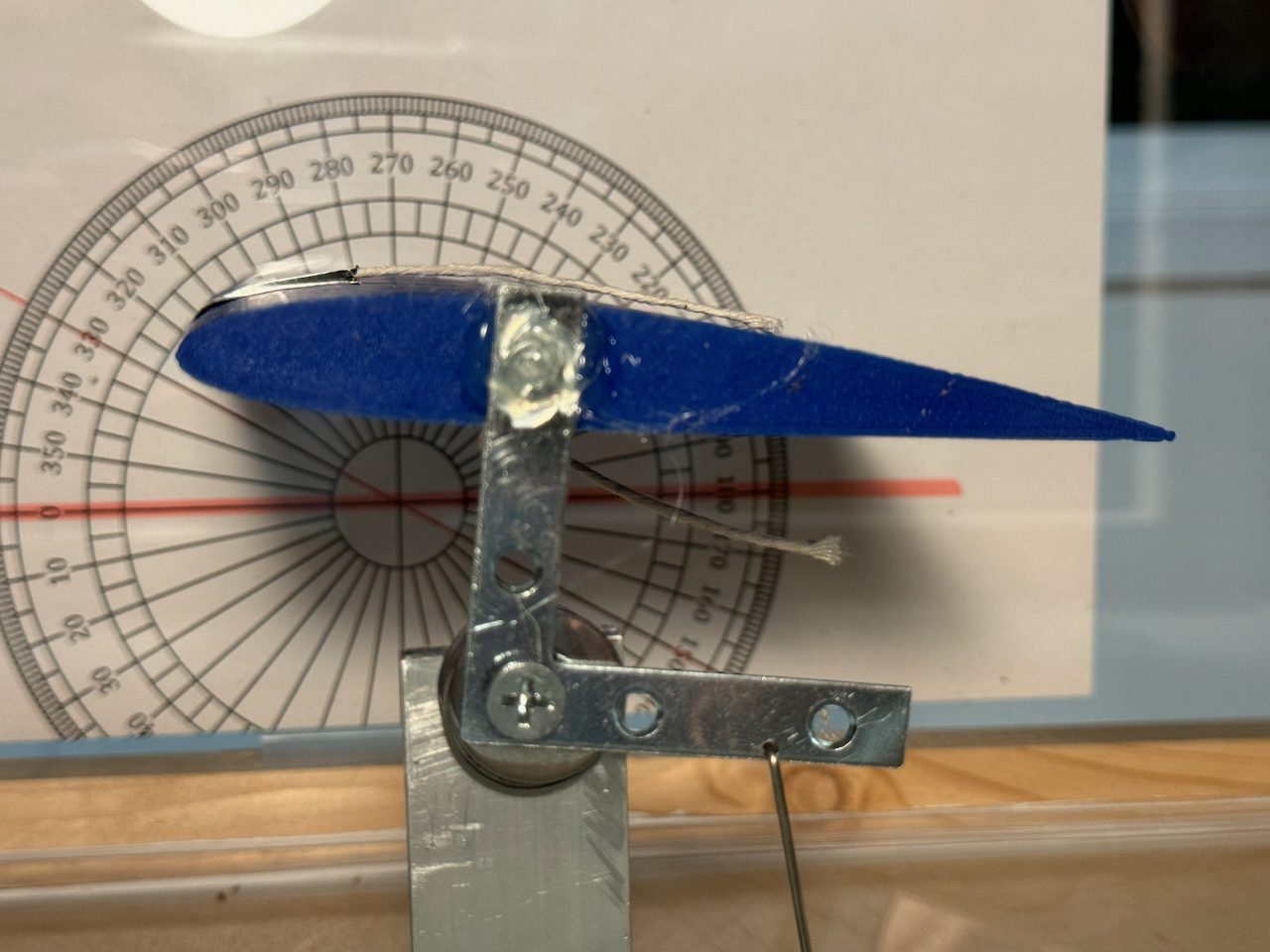
I then decided to create a better airfoil with my 3D printer. Using my CAD software, I downloaded the NACA 2412 (Cessna 172) and slightly modified it to print a 8″ wide by 4.5″ deep airfoil.

I added a metallic pivot alongside the servo attachment point to control the airfoil’. An interesting addition was the integration of a printed protractor, facilitating precise adjustments and measurements. Moreover, I employed small strings across the wing’s surface, a simple yet effective method to visualize the airflow dynamics and pinpoint the onset of stalls.

Here is a video showing the angle of attack slowing increasing and the airflow slowly separating until the airfoil stalls about 37 seconds into the video (watch the string moving towards the trailing edge of the wing):
Wind Tunnel Build Series
- Introduction: Building a Low-Speed Wind Tunnel
- Part 1: The Test Chamber
- Part 2: The Diffuser
- Part 3: The Concentrator
- Part 4: The Measuring Station
- Part 5: Setting up Arduino
- Part 6: First Experiments and Improvements
- Fine Tuning and Experiments